Line of Action of Equivalent Point Force (pp. 78-84)
Now we have the magnitude, and sometimes that might be enough but usually we need to also know the line of action. We find that by taking a moment to examine Fig. 68
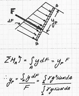
Fig. 68 Line of action of equivalent point load (equivalent to the actual distributed load)
We will simply require the moment generated by the total force we just determined (equivalent point load) to be equal the the moment generated by the distributed force (actual distributed load).
Choosing the upper edge of the plate as a rotational axis we have
Rearrangement gives
Simplification gives
The value \(I_x\) is the moment of inertia about the \(x\) axis. We will then recall the parallel axis theorem to find the value in terms of our centroidal locations
Where \(I_0\) is the moment of inertia about the plate centroid (tabulated for common geometric shapes).
The nice thing is that this calculus will work fine for any surface (shape and orientation), but at the expense of having to perform analysis to find the functions to integrate (or do numerical integrations which is easier if we can describe the geometry)
Below are some example applications of the force and line-of-action expressions follow.
Example 1: Concrete retaining wall form specification
Assuming that concrete behaves as a liquid (\(\gamma = 150\frac{lbf}{ft^3}\)) just after placement, determine the force per foot of length exherted on a form by the concrete if it is poured into forms for a wall that is to be 9 feet tall.
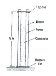
Fig. 69 Concrete retaining wall form design
If the forms are held in place as shown in Fig. 69, with ties between vertical braces spaced every 2 feet, what force is exherted on the bottom tie?
Now recall our problem protocol.
State the problem
Sketch the situation (sketching no matter how ugly helps organize thoughts!). Identify (list) known quantities
Identify (list) unknown quantities
Identify (list) governing principles and equations that appear relevant to the problem
Starting from one or more governing principles and the known quantities solve for the unknowns.
Validate/discuss results
State the problem
Essentially same as above, but there is some simplification in Fig. 70
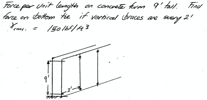
Fig. 70 Concrete retaining wall form design, problem statement
Sketch the situation
A sketch of one side of the form is shown in Fig. 71
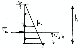
Fig. 71 Concrete retaining wall FBD and force identification.
Using the sketch as a guide our known quantities are the dimensions, the specific weight of concrete as a liquid.
Identify (list) unknown quantities
The unknown quantities are the resultant force (the equivalent point load) \(F_R\). per unit length.
Identify (list) governing principles
hydrostatic equation of a liquid
centroid of a rectangle (to find magnitude of the pressure force)
centroid of a triangle (to find point of application in the pressure prism
moment balance to find how force is resisted by the ties
Solve for the unknowns
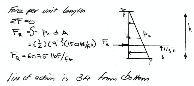
Fig. 72 Solve for pressure force per unit length (foot of wall)
Fig. 72 shows the analysis and solution for pressure force and line of application for each foot of wall.
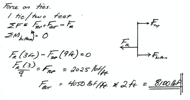
Fig. 73 Solve for load distribution in upper and lower ties per unit length (foot of wall)
Fig. 73 shows the analysis and solution for load distribution in the ties for each foot of wall. Each tie pair must support 2-feet of wall (except for the end pairs) which gives the end result of 8100 lbs for the lower ties. Using this value we can decide what size rods to use as ties. For example
1/4 all-thread tensile strength has an upper limit strength of 150000 psi, so we multiply by the rod cross sectional area to see if it is strong enough.
1/2 all-thread tensile strength has an upper limit strength of 60000 psi, so we multiply by the rod cross sectional area to see if it is strong enough.
The scripts to compute the strength are below; 1/4-inch is suitable for the upper ties; 1/2-inch is plenty strong for the lower ties.
import math
tensile = 150000 #psi
diameter = 0.25 #inches
area = 0.25*math.pi*diameter**2 #area in inches
force = tensile*area
print('1/4 inch tie rod strength = ', round(force,3), 'lbs')
1/4 inch tie rod strength = 7363.108 lbs
import math
tensile = 60000 #psi
diameter = 0.50 #inches
area = 0.25*math.pi*diameter**2 #area in inches
force = tensile*area
print('1/2 inch tie rod strength = ', round(force,3), 'lbs')
1/2 inch tie rod strength = 11780.972 lbs
Forces on Submerged Objects
The integral methods will always work, but an easier approach for common geometries is a projection of volumes approach.
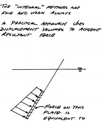
Fig. 74 Force diagram submerged plate
The idea is that the distributed force as depicted in Fig. 74 is equivalent to the vertical and horizontal component forces depicted in Fig. 75. The horizontal component is found using the hydrostatic equation applied to the projection of the object onto a vertical plane.
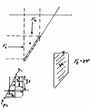
Fig. 75 Resultant forces by displacement
The vertical component is found as the weight of the volume of liquid above the object.
