Conservation of Linear Momentum
Lesson Outline
Measuring velocity and pressure using pitot-static systems (Bernoulli application)
Examples of CV applications for continunity
CV Relationships for momentum
Background
Linear momentum relates forces to changes in translational velocity. Reynolds Transport Theorem is used to generate integral expressions of momentum balances in a control volume.
Linear Momentum
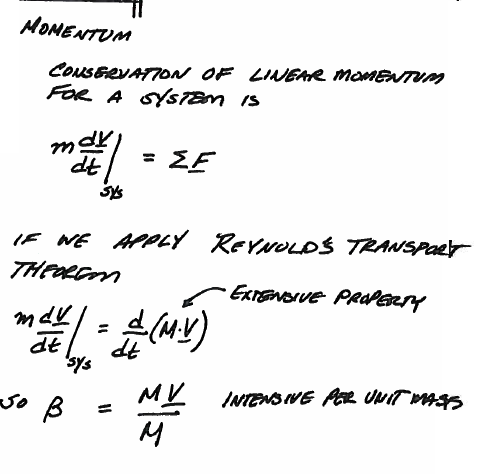
Caption
momentum-p1-1 relates the extensive property of linear momentum for a system to the intensive property of momentum per unit mass which is the velocity vector. momentum-p1-2 extends to the intensive property of momentum per unit volume which is the product of density and velocity vector \(\rho \bar V\)
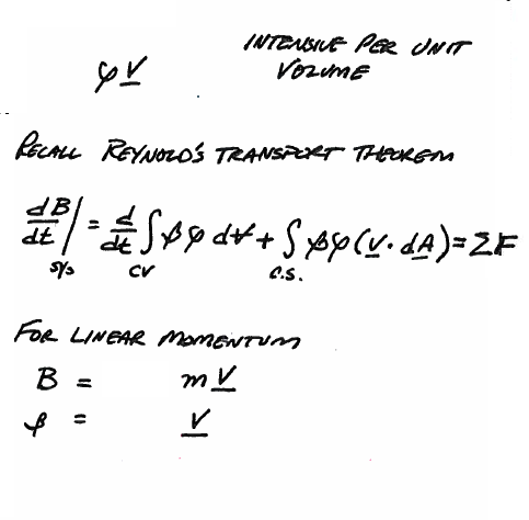
Caption
The result of application of theReynolds Transport Theorem to the linear momentum term is an integral equation that relates the sum of external forces to the rate of change of linear momentum in the control volume plus the net momentum leaving across the control surface as depicted in momentum-p1-3
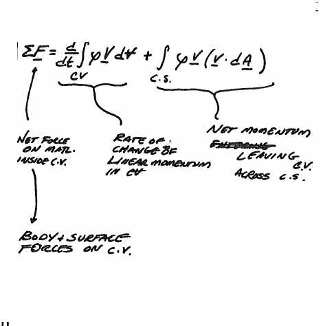
Caption
Note
Application of momentum principles uses three primary principles:
Select an inertial (non-acelerating) reference frame
Indicate positive and negative coordinate directions
Draw the CV/CS and indicate
Forces
Velocities
Outward pointing area vectors (\(dA \bar\) vectors)
Example 1: Application of Momentum to a Jet Pump
A water jet pump has jet area of 0.01 sq.m. and jet speed of 30 m/s. The jet is within a secondary stream of water having speed 3 m/sec. The total duct area is 0.075 sq.m. The water is completely mixed in the pump and exits at uniform velocity; find the speed at the pump exit and the pressure rise in the pump.
The problem statement is explicitly repeated in momentum-ex1-1
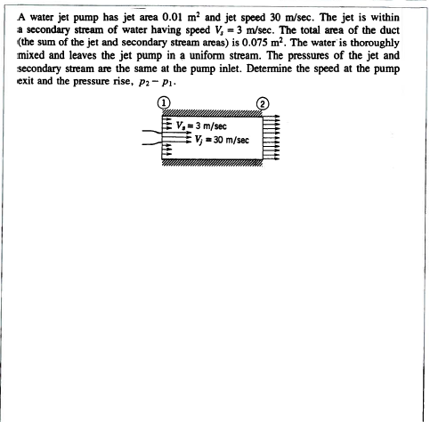
Caption
Apply our problem solving protocol as in momentum-ex1-2
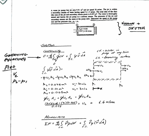
Caption
Note on the CV diagram to draw:
the +/- directions
the CV/CS
the \(\bar dA \) vectors, and
the \(\bar V \) vector(s)
Then apply continunity and momentum to find the unknown values as in momentum-ex1-3
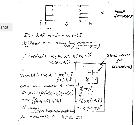
Caption
# computational thinning
u_jet = 30.0
u_approach = 3.0
a_jet = 0.01
a_approach = 0.065
a_total = 0.075
rho = 1000.0
# continunity
u_exit = (u_jet*a_jet+u_approach*a_approach)/a_total
# momentum
delta_p = -(rho/a_total)*(a_total*u_exit**2 - a_jet*u_jet**2 - a_approach*u_approach**2)
# results
print("Pump exit velocity ",round(u_exit,3),"     meters per second")
print("Added pressure     ",round(delta_p,3)," Pascals")
Pump exit velocity  6.6      meters per second
Added pressure      84240.0  Pascals
Example 2: Forces in a Pipe Fitting
Consider a pipe fitting as depicted in momentum-ex2-1
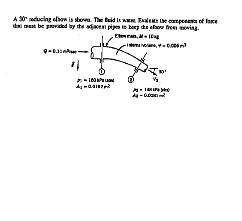
Caption
Apply our problem solving protocol as in momentum-ex2-2
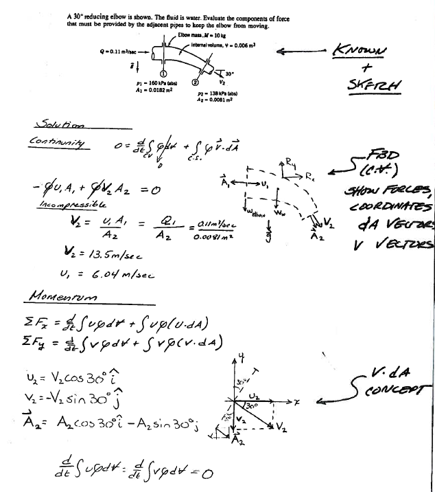
Problem Solving Protocol: Sketch, CV Definition, Governing Principles, Knowns and Unknowns
Apply our analysis tools as in momentum-ex2-3
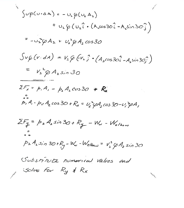
Application of linear momentum in the two coordinate directions
Applications of Momentum
Momentum is used to find forces on objects that are changing the flow field.
Forces are important in things like
Bridge piers
Wind turbine support columns
Retaining walls
Dams
As an example consider the force on a sluice gate (underflow from a powerhouse) as depicted in momentum-p2-1
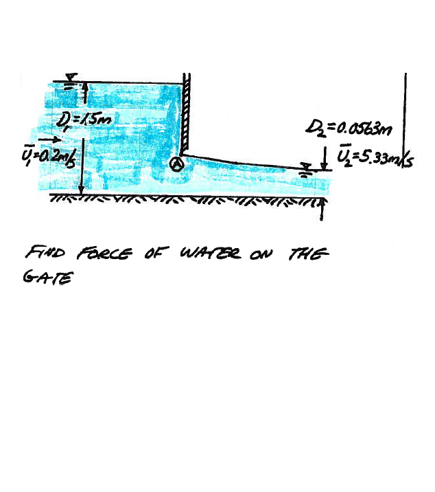
Schematic elevation view of a sluice gate
Upon first inspection one would be tempted to treat the gate as a submerged plate and use hydrostatic calculations, except at point A the pressure is atmospheric, same as at the free surface just upstream of the gate, so the required conditions for hydrostatic analysis do not apply in this case.
So instead of trying to find pressure on the gate, find force of gate on the water, then by eth equal-opposite action-reaction (Newtons’s 2nd law) we can find force of water on the gate .
A first step is to draw a control volume as depicted in momentum-p2-2
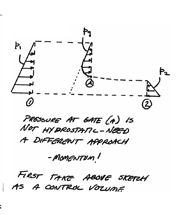
CV/CS for sluice gate
Using the figure as a guide draw:
the +/- directions
the CV/CS
the forces
the \(\bar dA \) vectors, and
the \(\bar V \) vector(s)
The resulting sketch is shown in momentum-p2-3

CV/CS for sluice gate
Some assumptions are in order; in particular the distance upstream and downstream are relatively small (a few hundred feet) and the frictional contribution is small by virtue of having only a short distance to act, so we neglect the frictional component. Using the velocity and area directions to resolve the inner products in the flux integrals produces the diagram in momentum-p2-4
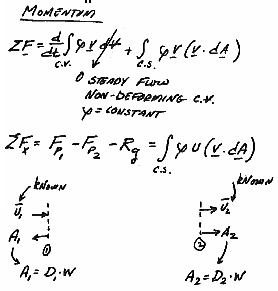
CV/CS for sluice gate
The two pressure forces are some distance from the gate and are hydrostatic and computed using that equation.
\(p = \gamma \bar h\) as depicted in momentum-p2-5
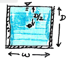
Pressure force diagram
momentum-p2-6 is a skecth showing the collection of forces on the CV
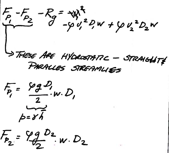
Forces on CV
momentum-p2-7 completes the analysis; then we can generalize for any sluice gate (in rectangular channles) using ENGR-1330 principles as shown in the script below.
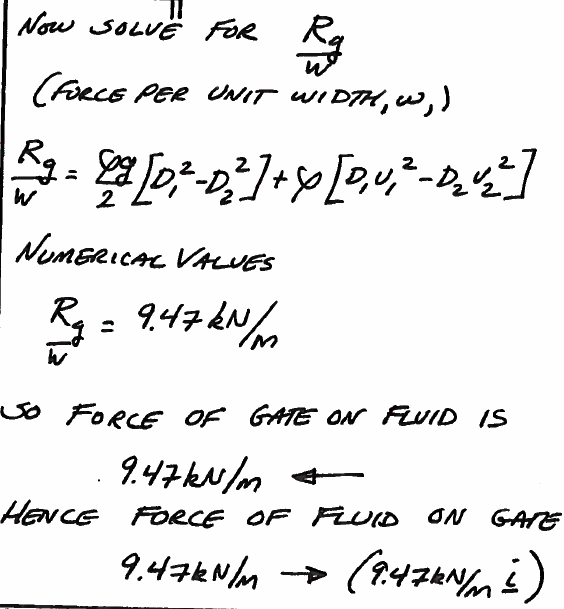
Forces on CV
Sluce Gate Calculations
d1 = 1.5 # depth upstream
d2 = 0.0563 # depth downstream
u1 = 0.2 # upstream velocity
u2 = 5.33 # downstream velocity
rho = 1000.0 # density
g = 9.8 # gravitational acceleration
w = 1.0 # channel width
Rg = (0.5*rho*g)*(d1**2 - d2**2)+rho*(d1*u1**2 - d2*u2**2)
print('Upstream Depth',d1,' m')
print('Upstream Speed',u1,'m/s')
print('Downstream Depth',d2,' m')
print('Downstream Speed',u2,'m/s')
print('Force/width',round(Rg,2),'N/m')
Upstream Depth 1.5  m
Upstream Speed 0.2 m/s
Downstream Depth 0.0563  m
Downstream Speed 5.33 m/s
Force/width 9470.05 N/m
Example 3 Shallow Wave Speed in a Channel
Consider a shallow wave in a rectangular channel as in momentum-ex3-1
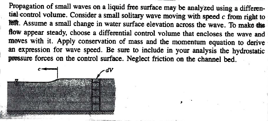
Problem Statement
First we draw a control volume as in momentum-ex3-2
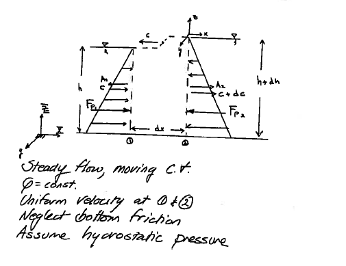
Sketch
Then apply continunity to find the apparent velocities as in momentum-ex3-3
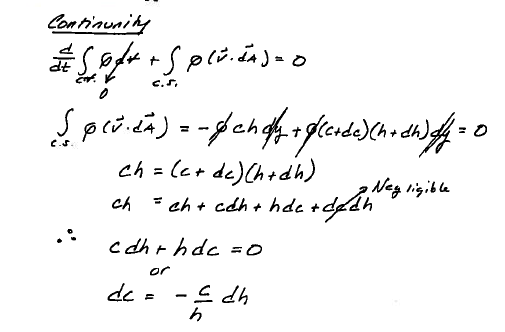
Continunity application
Then apply momentum as in momentum-ex3-4
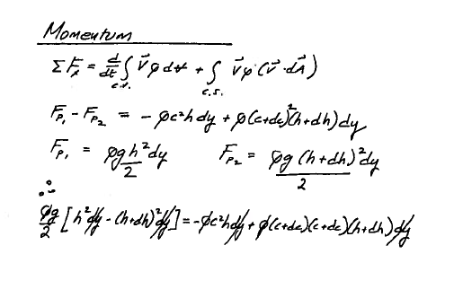
Momentum application
Complete the analysis to find the shallow wave speed as in momentum-ex3-5
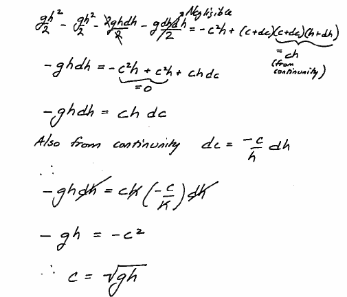
Analysis results
Readings
CE-3305-2022-1 Syllabus. http://54.243.252.9/ce-3305-webroot/0-Syllabus/ce-3305-2022-1-syllabus.html
Hibbeler, R.C, Fluid Mechanics, 2ed. Prentice Hall, 2018. ISBN: 9780134655413 pp. 293-355
DF Elger, BC Williams, Crowe, CT and JA Roberson, Engineering Fluid Mechanics 10th edition, John Wiley & Sons, Inc., 2013. (placeholder file to get links working). http://54.243.252.9/ce-3305-webroot/3-Readings/EFM-9.pdf
Cleveland, T. G. (2014) Fluid Mechanics Notes to Accompany CE 3305 at Jade-Holshule (TTU Study Abroad 2015-2019), Department of Civil, Environmental, and Construction Engineering, Whitacre College of Engineering. http://54.243.252.9/ce-3305-webroot/3-Readings/ce3305-lecture-9.pdf
