Download this file as a Jupyter Notebook@ http://54.243.252.9/ce-3372-webroot/2-Exercises/PR2/PR2.ipynb
PR-2
Copyright © 2021 Theodore G. Cleveland
Purpose:
Assess hydraulic viability of street-only drainage; suggest modifications to the drainage (design a storm sewer) to satisfy statuatory requirements; initial cost estimation to build a storm sewer. Report results in an engineering design report, with references, exhibits, and recomendations.
Problem Statement
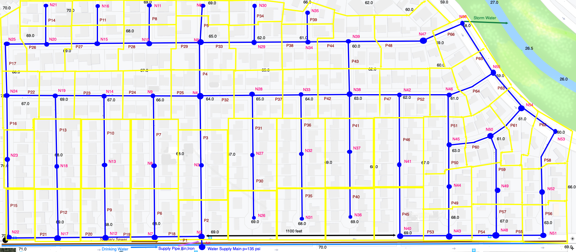
A small residential subdivision (SomewhereUSA) is depicted in the figure below; plotted on the figure is a layout of a water distribution system for the subdivision.

A drainage system will discharge stormwater in the North-East corner of the study area (green arrow) into the stream indicated by the blue line segment. The initial design is to convey stormwater in the streets depicted on the figure; however it is likely there will be substantial ponding, so a storm sewer system will be installed.
Using the United States Environmental Protection Agency, SWMM hydraulic and water quality simulator, model the existing drainage system and use the results to inform a storm sewer design that will drain the subdivision and keep ponding to less than 6-inches in the streets.
Deliverables
- An engineering preliminary design report for the proposed water distribution network.
The project report for the the drainage system should be written as an intended component for an overall design report for the subdivision (water supply, storm water, sanitary collection)
The project report component should contain:
- An estimate of the anticipated 5-year, 3-hour design storm for Harris County; with supporting references.
- A node-pipe layout for the storm sewer system, overlain on the subdivision map. The pipe nodes will be treated as inlets.
- This layout is not depicted on the figure; you will have to design the storm drain system! You can use elevations from PR1 as the land-surface elevation for your drainage design.
- Inlet calculations to determine the drainage area that a single 10-foot curb-on-grade inlet would be expected to capture. Use this value to determine inlet spacing (and location) along the streets.
- The burial depths required for the storm drain mains and laterals.
- The drainage pipe diameters and materials.
- Produce a node invert elevation table and land surface elevation table for the node locations.
- A hydraulic model that simulates the flow and water surface elevation in the drainage system. The model will use sub-catchments (and CN method) for hydrology, these will attach to the nodes, which in turn connect pipes.
- A hydraulic simulation, using “kinematic wave” option in SWMM, for the design storm.
- A hydraulic simulation, using “dynamic wave” option, with “inertial terms == IGNORE”, in SWMM for the design storm. The outfall in this simulation is “NORMAL”.
- A hydraulic simulation, using “dynamic wave” option, with “inertial terms == IGNORE”, in SWMM for the design storm. The outfall in this simulation is “FIXED” with the stage (elevation) set to 50 feet.
- A cost estimate for the inlets, pipes, junctions and any special components that are required based on the hydraulic simulation.
- An estimate of the trenching requirements to install the storm sewer.
- A summary, interpretation, and recommendations based on the hydraulic modeling – esp. the impact of backwater (the 3rd simulation conditions).
References
Rossman, L. (2000). EPANET 2 users manual. Technical Report EPA/600/R-00/057,U.S. Environmental Protection Agency, National Risk Management Research LaboratoryCincinnati, OH 45268.
CE 3372 – Water Systems Design Design Project (pre-2021) problem statement http://54.243.252.9/ce-3372-webroot/2-Exercises/PR1/ce_3372_2020-3-project.pdf
CE 3372 - STORM WATER DRAINAGE SYSTEM ANALYSIS AND DESIGN FOR CROSBY, TEXAS (circa 2015) Example Project Report http://54.243.252.9/ce-3372-webroot/2-Exercises/PR2/Project2_Goby2.pdf
Useful Images
Base map without water distribution system overlay http://54.243.252.9/ce-3372-webroot/2-Exercises/PR2/SomewhereUSABaseMap.png
Base map with a topographic map overlay http://54.243.252.9/ce-3372-webroot/2-Exercises/PR2/ES-2_sample-map.png