Download this file as a Jupyter Notebook@ http://54.243.252.9/ce-3372-webroot/2-Exercises/ES8/PR1.ipynb
PR-1
Copyright © 2021 Theodore G. Cleveland
Purpose:
Assess hydraulic viability of a distribution network design; suggest modifications to the design to satisfy statuatory requirements; initial cost estimation to build network. Report results in an engineering design report, with references, exhibits, and recomendations.
Problem Statement
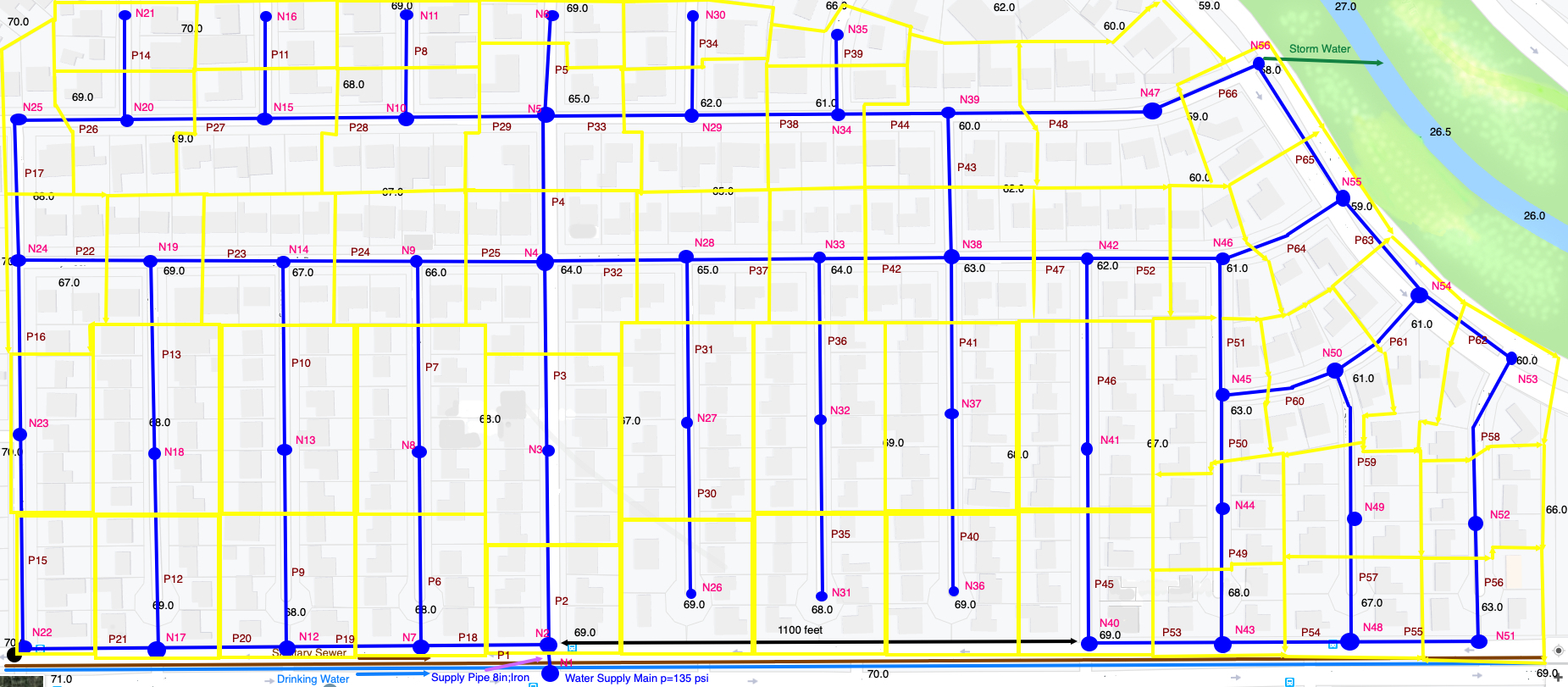
A small residential subdivision (SomewhereUSA) is depicted in the figure below; plotted on the figure is a layout of a water distribution system for the subdivision. The blue line segments are pipes (ductile iron) and are labeled (P1, P2, . . . ). The blue circles are nodes and are labeled (N1, N2, . . . ). The yellow polygons represent the demand lots assigned to each node. For example, node N2 supplies the six (6) individual lots located near the node.

The distribution system is connected to the supply main at node N1. This large water main reliably supplies water at 135 psi. pressure. The pipe connecting node N1 to N2 is an 8-inch diameter, ductile iron pipe. The remaining pipes are 2-inch diameter, ductile iron pipe.
The water main delivers treated drinking water with a chloramine disinfectant residual of 8 ppm. The water supply line (as shown) is nearly horizontal with a bottom (of the pipe) elevation of 52-feet.
Using the United States Environmental Protection Agency, EPANET hydraulic and water quality simulator, model the system and evaluate its suitability for the subdivision. Use RG-195 and the San Marcos Texas manual for statutory requirements as necessary
Deliverables
- An engineering preliminary design report for the proposed water distribution network.
The project report for the drinking water system should be written as an intended component for an overall design report for the subdivision (water supply, storm water, sanitary collection)
The drinking water supply report should address:
- The required burial depths required for the water distribution pipes.
- The minimum pipe diameters required on the water utility side of the meter.
- A node-pipe layout map/drawing, overlain on the subdivision map.
- The pipe layout can be a skeleton system (you do not need to show every meter -- demands should be grouped from 6-8 houses/node).
- Produce a node elevation table (and land surface elevation table)
- A node contour map.
- Demand estimates (describe the values and methods).
- Fire hydrant locations.
- A hydraulic model that simulates the flow and pressure in the network.
- A hydraulic simulation under normal flow (no fire) conditions.
- The model must be interpreted and the minimum and maximum pressures identified (along with their locations). If special items are required (pressure-reducing-valves; booster pumps; $\dots$) these must be described and their need explained.
- A hydraulic simulation under (reasonable) fire-flow conditions.
- The model must be interpreted and the minimum and maximum pressures identified (along with their locations).
- An evaluation of water age in the network under normal conditions.
- Identification of disinfection residual minimum location in the network under normal conditions.
- A cost estimate for the pipes, valves, fire hydrants, water meters, and any special components that are required based on the hydraulic simulation.
- An estimate of the trenching requirements to install the network
References
Rossman, L. (2000). EPANET 2 users manual. Technical Report EPA/600/R-00/057,U.S. Environmental Protection Agency, National Risk Management Research LaboratoryCincinnati, OH 45268.
CE 3372 – Water Systems Design Design Project (pre-2021) problem statement http://54.243.252.9/ce-3372-webroot/2-Exercises/PR1/ce_3372_2020-3-project.pdf
CE 3372 - WATER DISTRIBUTION SYSTEM ANALYSIS AND DESIGN FOR CROSBY, TEXAS (circa 2015) Example Project Report http://54.243.252.9/ce-3372-webroot/2-Exercises/PR1/Project1_GoBy1.pdf