Download this file as a Jupyter Notebook@ http://54.243.252.9/ce-3372-webroot/2-Exercises/ES5/ES5.ipynb
ES-5
Copyright © 2021 Theodore G. Cleveland
Purpose:
Application of energy and pumping concepts; System curve; Operating point
- Compute head loss as function of discharge in a pipe (system curve).
- Determine pump operation point from a pump curve.
- Develop expertise in interpreting output to answer specific hydraulic questions
Exercise 1
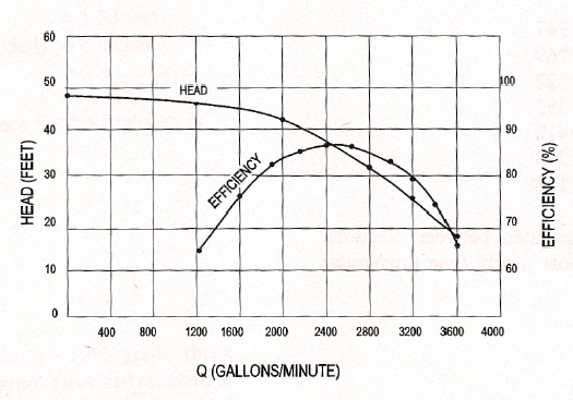
A water supply system draws from a river at an elevation of 800-feet and delivers the water to a storage reservoir at elevation 820-feet. The supply pipeline is a 1000-foot long, 10-inch diameter, cast iron pipe. A single pump with the pump characteristic curve in Figure 1 is used to fill the reservoir.
Determine:
- Sketch the system described in the problem statement.
- Inlet and outlet minor loss coefficients, cite your source of minor loss coefficients.
- The roughness height for use in head loss calculations, cite your source of roughness height.
- The energy equation for the system (system curve).
- The system loss for a discharge of 1200, 1600, 2000, 2400, and 2800 gallons-per-minute.
- Show the calculation of Reynolds number for the different flow rates.
- Show the determination of the friction factors.
- The operating discharge for the system using the supplied pump curve.
- The electric power supplied to the pump to lift the water at the operating point.
Help
Exercise 2
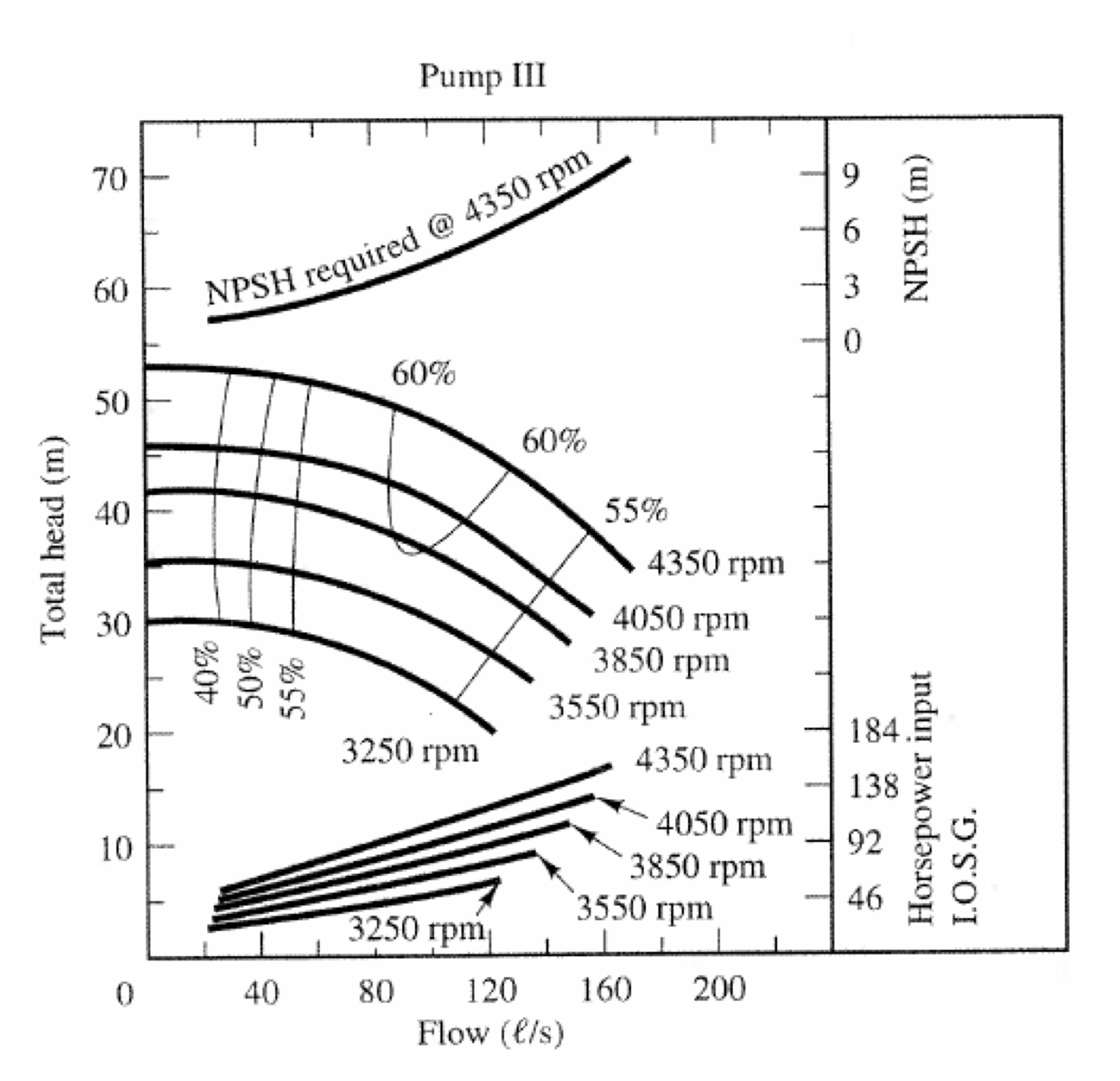
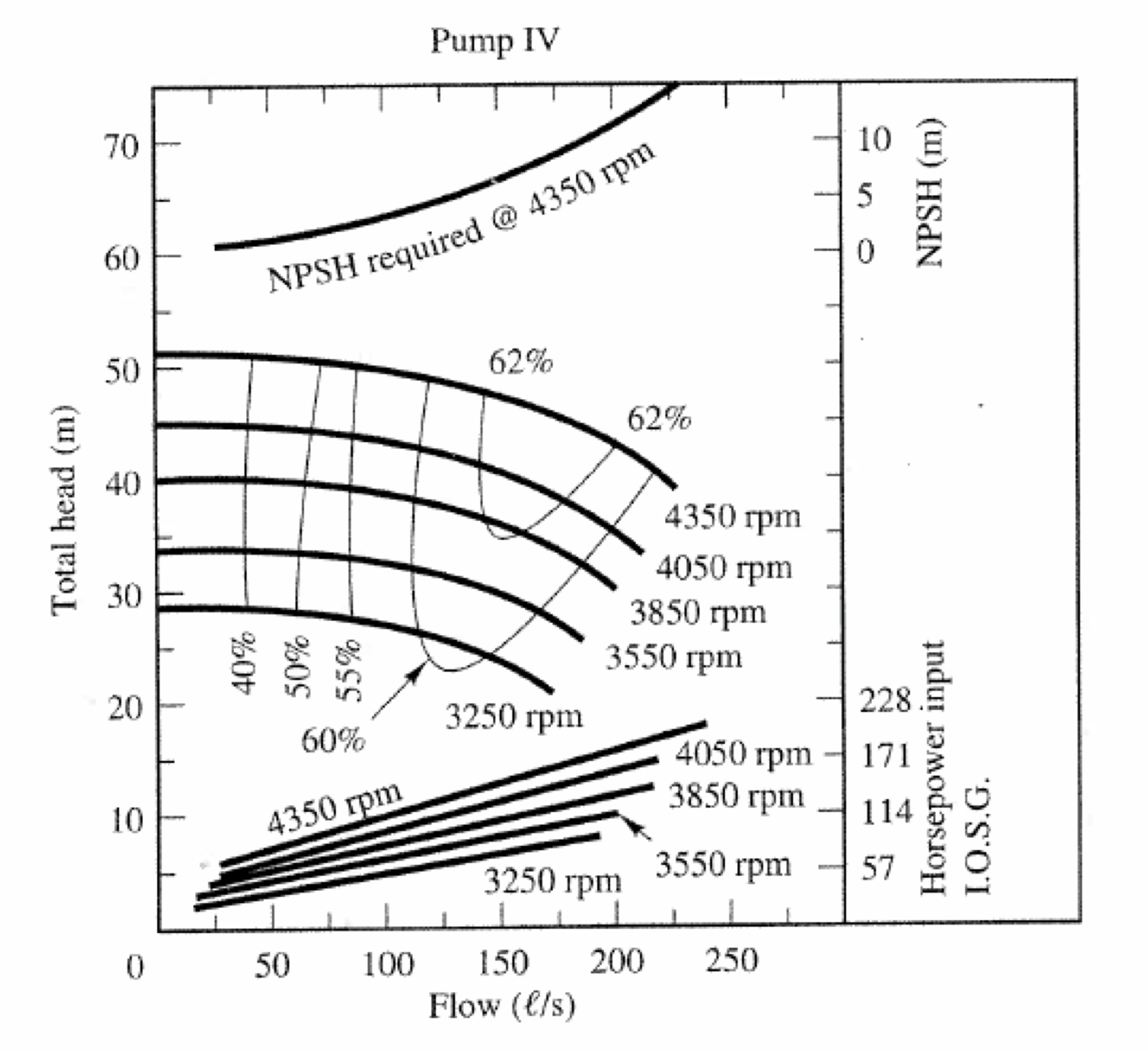
Water is to be pumped at a rate of 70 liters per second in a 1-kilometer meter long, 200 millimeter diameter pipeline between two reservoirs with an elevation difference of 26 meters. A schematic of the system is shown on Figure 2. The kinematic viscosity of water in the system is $\nu = 1 \times 10^{6} m^2/s$ The roughness height of the steel pipe is $\epsilon = 0.045 mm$.
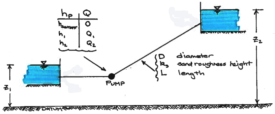
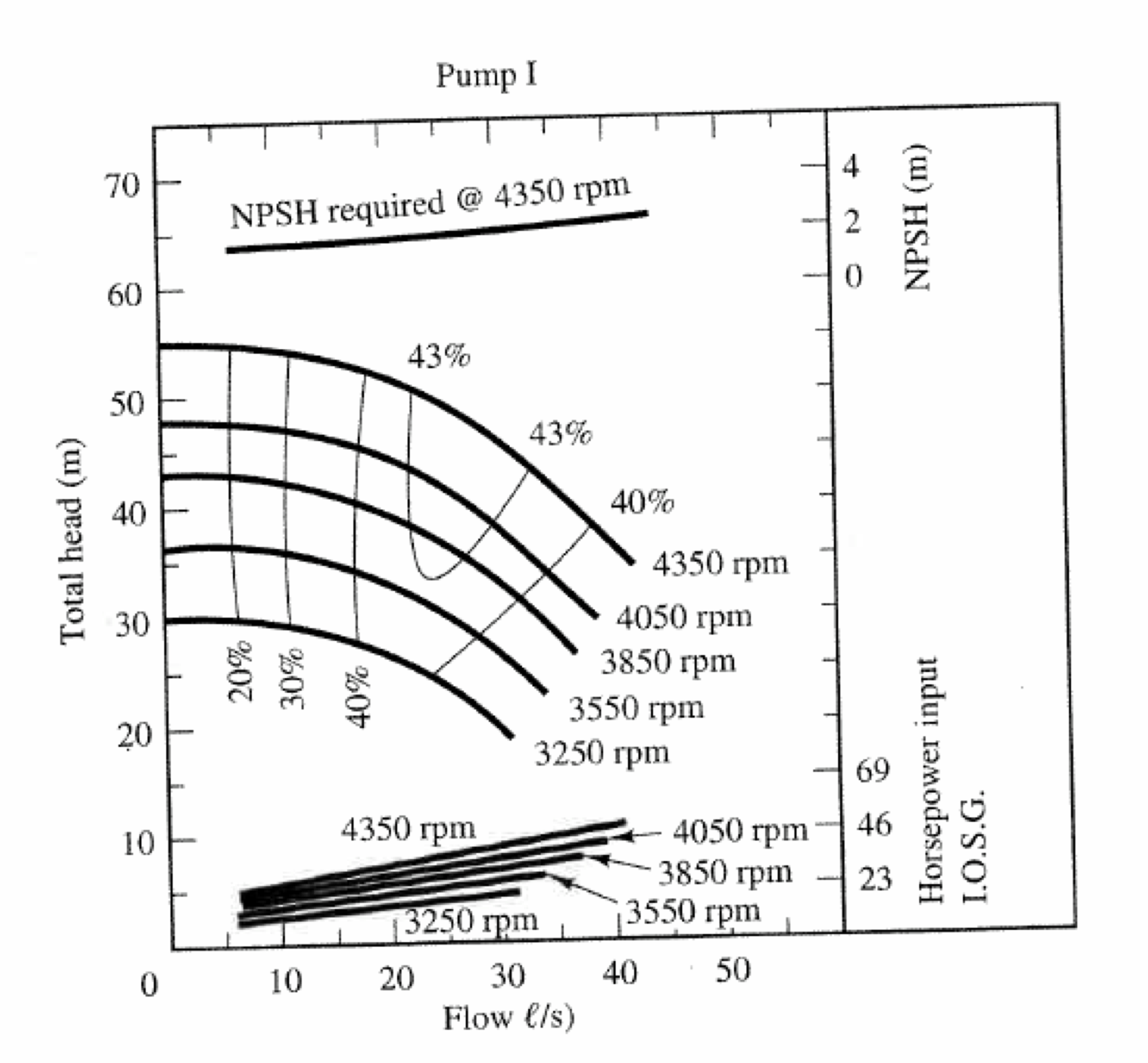
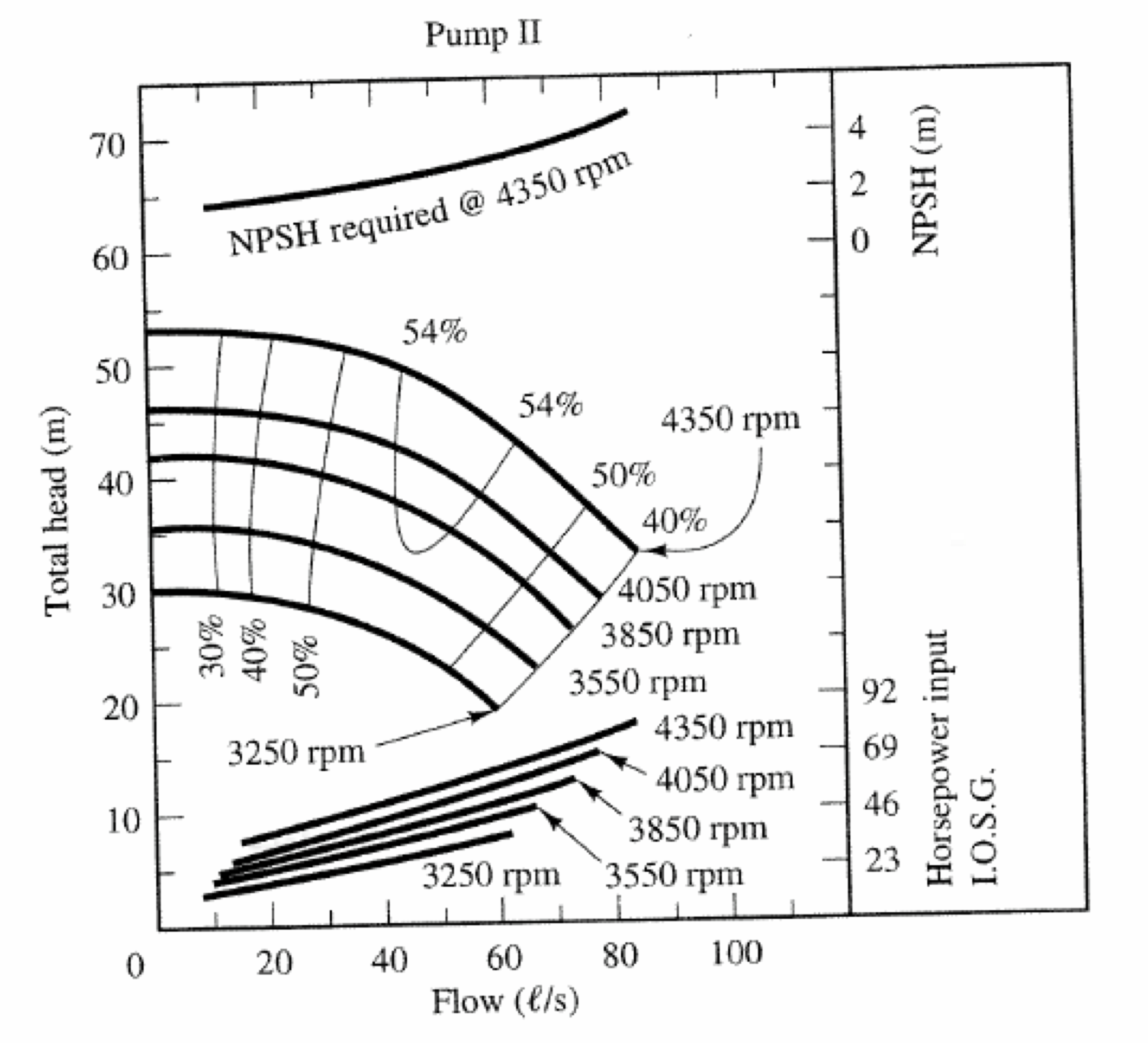
- Select a pump type (from the four curves below) that can supply the required head at the required flow rate.
- Write the impeller speed for the pump in your selection.
- Indicate (label on the appropriate pump curve) the operating point of the pump you selected.
- Estimate the required NPSH for the pump you choose.
- Demonstrate that $NPSH_a > NPSH_r$ for your pump choice.
Deliverables:
A brief memorandum with your solutions, showing the requested equations, head loss calculations, and pump operating points.
References
- Gupta, R. S. 2017. Hydrology and Hydraulic Systems. Waveland Press, Inc. pp. XX-XX
