Download this file as a Jupyter Notebook@ http://54.243.252.9/ce-3372-webroot/2-Exercises/ES4/ES4.ipynb
ES-4
Copyright © 2021 Theodore G. Cleveland
Purpose:
Demonstrate application of head loss models in analysis of pressure and flow in water distribution systems.
Background
Equation 1 below is the Hazen-Williams discharge formula in US Customary Units.
$$ Q=1.318~C_h~A~R^{0.63}~S^{0.54}~~~~~[1]$$where;
- $Q$ is the discharge in $\frac{ft^3}{sec}$;
- $A$ is the cross section area of pipe in $ft^2$;
- $D$ is the pipe diameter.;
- $C_h$ is the Hazen-Williams friction coefficient (depends on pipe roughness);
- $R$ is the hydraulic radius in $ft$; and
- $S$ is the slope of the energy grade line ($\frac{h_f}{L}$); $L$ is the length of pipe.
Equation 2 below is the Hazen-Williams discharge formula in SI Units.
$$ Q=0.849~C_h~A~R^{0.63}~S^{0.54}~~~~~[2]$$where;
- $Q$ is the discharge in $\frac{m^3}{sec}$;
- $A$ is the cross section area of pipe in $m^2$;
- $D$ is the pipe diameter.;
- $C_h$ is the Hazen-Williams friction coefficient (depends on pipe roughness);
- $R$ is the hydraulic radius in $m$; and
- $S$ is the slope of the energy grade line ($\frac{h_f}{L}$); $L$ is the length of pipe.
Equation 3 below is a formula to estimate the required pipe diameter for a particular discharge, head loss, and roughness (Swamee and Jain, 1976).
$$D= 0.66[k^{1.25}_s \times (\frac{LQ^2}{gh_f})^{4.75} + \nu Q^{9.4} \times (\frac{L}{gh_f})^{5.2}]^{0.04} ~~~~~[3]$$where;
- $D$ is the pipe diameter;
- $k_s$ is the pipe roughness height;
- $L$ is the length of pipe;
- $g$ is the gravitational acceleration constant;
- $Q$ is the discharge in $L^3/T$;
- $h_f$ is the head loss in the pipe;
- $\nu$ is the viscosity of liquid in the pipe;
Exercise 1
a) Look up the Hazen-Williams loss coefficient ($C_h$) for enamel coated, steel pipe and cite your data source.
b) Estimate the head loss in a 10,000 foot length of 5-foot diameter, enamel coated steel pipe that carries carries 60$^o$F water at a discharge of 295 cubic-feet per second(cfs), using the appropriate Hazen-Williams head loss model.
Exercise 2
a) Look up the Hazen-Williams loss coefficient ($C_h$) for Acrylonite Butadiene Styrene(ABS) pipe and cite your data source.
b) Estimate the head loss in a 3,050 meter length of 1.5-meter diameter, ABS pipe that carries carries 20$^o$C water at a discharge of 8.35 cubic-meters per second (cms),using the appropriate Hazen-Williams head loss model.
Exercise 3
a) Find the viscosity for water at 60$^o$F. Cite the source of your value.
b) Find the sand roughness height of cast-iron pipe. Cite the source of your value.
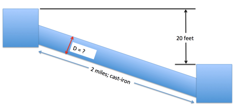
c) Use the Swamee and Jain (1976) equation to estimate the diameter of a cast-iron pipe needed to carry 60$^o$F water at a discharge of 10 cubic-feet per second (CFS) between two reservoirs 2 miles apart with an elevation difference between the water surfaces in the two reservoirs of 20 feet as depicted in Figure 1 below.

| Figure 1. Pipeline connecting two reservoirs | ||
|---|---|---|
Exercise 4
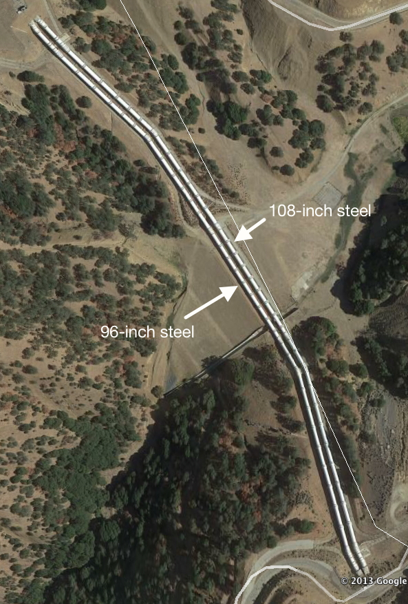
Figure 2 is an aerial image of a parallel pipeline system in California.

| Figure 2. Parallel Pipeline System | ||
|---|---|---|
The left pipeline is a 96-inch diameter steel pipe, whereas the right pipeline is a 108-inch diameter steel pipe. Water at 50$^o$F has kinematic viscosity of $1.45 \times 10^{−5}~ft^2/s$. The sand roughness of ductile iron is $1.64 \times 10^{-4}$ ft. If the head difference for the one-mile long pipelines between the thrust blocks is 120 feet, determine the discharge in the 96-inch diameter pipe in cubic-feet-per-second.
Deliverables:
A 1-2 page memorandum-type report with your solutions, showing the arithmetic used and listing data sources employed.
References
- Swamee and Jain, A. K., 1976. Explicit equations for pipe-flow problems. ASCE J. of Hyd.Div., 102(HY5) pp. 657-664
