Download this file as a Jupyter Notebook@ http://54.243.252.9/ce-3372-webroot/2-Exercises/ES12/ES12.ipynb
ES-12
Copyright © 2022 Theodore G. Cleveland
Purpose:
Apply rational equation model process to size conduits for a storm drain system.
Problem Data
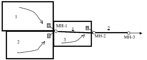
Three drainage areas that drain to the inlets connected to the pipes as shown in Figure 1. A stormwater drainage system is being designed to carry the flow from the three areas.

Table 1 lists drainage area information.

Table 2 is a list of pipe connectivity, flow lengths, design slopes, and pipe roughness data.

Equation 1 is the 10-year ARI intensity equation for the area, where $I$ is intensity in inches-per-hour, and $T_c$ is the averaging time, in minutes. Depending on the location in the system it may be just the local inlet time, or a time of concentration that includes upstream contributions and pipe travel time.

The allowable velocity at design flow is between 2 and 10 feet-per-second. The pipes are to be sized so they flow $\frac{1}{2}$ full at the design discharge.
Problem Statement
Using the supplied problem data, and assuming the 10-year ARI is the design standard for the system:
- Determine the design flow rates in cfs for each pipe
- Determine the associated pipe diameters in inches for both pipes.
Deliverables:
A brief report with your solution, showing the requested values, any intermediate calculations, any additional data required, and its source.
References
- Gupta, R. S. (2017). Hydrology and Hydraulic Systems. Waveland Press, Inc. pp. 711-733
- Mays, L. W. (2011). Water-Resources Engineering. Wiley. pp. 613-635 http://54.243.252.9/ce-3372-webroot/3-Readings/Mays613-635/RationalMethodStormSewerDesign.PDF
