CE 3305 Engineering Fluid Mechanics
Spring 2024 Exam 3
LAST NAME, FIRST NAME
R00000000
Purpose :
Demonstrate ability to apply fluid mechanics and problem solving principles covering topics such as: Dimensional analysis and similitude; turbulent flow in closed conduits; pump system performance.
Problem 1
A smooth pipe prototype designed to carry crude oil:
- $D = 47$ inches
- $\rho= 1.75$ slugs/$ft^3$
- $\mu= 4 \times 10^{−4}~ lbf − s/ft^2$
is to be modeled with a smooth pipe 4 inches in diameter carrying water (T =60$^o$F ).
Determine:
- The mean velocity of the water in the model to ensure dynamically similar conditions, if the mean velocity in the prototype is to be 2 ft/s,?
sketch(s) here
list known quantities
list unknown quantities
governing principles
solution (step-by-step)
# script (code) here
discussion
Problem 2:
Experiments are performed to measure the pressure drop in a pipe with water at 20$^oC$ and crude oil at the same temperature. Data was gathered with pipes of two diameters, 5 cm and 10 cm for pressure drop per unit length of pipe, and are tabulated below:
| Liquid | Pipe Diameter (cm) | Velocity (m/s) | Pressure Drop (N/m$^3$) |
|---|---|---|---|
| Water | 5 | 1 | 210 |
| Water | 5 | 2 | 730 |
| Water | 5 | 5 | 3750 |
| Water | 10 | 1 | 86 |
| Water | 10 | 2 | 320 |
| Water | 10 | 5 | 1650 |
| Oil | 5 | 1 | 310 |
| Oil | 5 | 2 | 1040 |
| Oil | 5 | 5 | 5300 |
| Oil | 10 | 1 | 130 |
| Oil | 10 | 2 | 450 |
| Oil | 10 | 5 | 2210 |
The presure drop per unit length is postulated to be a function of pipe diameter, liquid density, liquid viscosity, and flow velocity as:
$$\frac{\Delta p}{L}=f(\rho,\mu,V,D)$$Perform a dimensional analysis to identify suitable $\pi-$groups and create a Jupyter Notebook to reduce the data and plot the results using the dimensionless values. Select an appropriate data model based on the plot.
Determine:
- Suitable $\pi-$groups to reduce the data to dimensionless values
- Plot the results using the dimensionless values.
- Propose an appropriate (linear, log-linear, parabolic, ...) data model based on the plot.
sketch(s) here
list known quantities
list unknown quantities
governing principles
solution (step-by-step)
# script (code) here
discussion
Problem 3:
The figure below is a schematic of a pumped-storage system. Water is pumped between the two reservoirs in a pipeline with the following characteristics: D = 300 mm, L = 50 m, f = 0.025, ΣK = 4.0. The radial-flow pump characteristic curve for a single pump is $H_p = 22.9 + 10.7Q -111Q^2$ where $H_p$ is in meters and $Q$ is in $\frac{m^3}{sec}$.

Determine:
- The discharge $Q_D$ and pump added head $H_D$ if $z_2 - z_1 = 40~m$ with three identical pumps operating in series.
sketch(s) here
list known quantities
list unknown quantities
governing principles
solution (step-by-step)
# script (code) here
discussion
Problem 4:
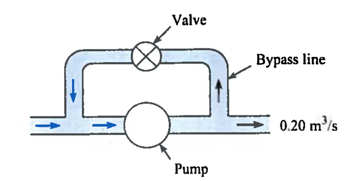
In the design of a lift station, a bypass line is often installed parallel to the pump so some liquid recirculates as shown on Figure 1. The bypass valve then controls the flow rate in the system.

The pump performance function is $$h_p = 100 - 100Q$$
where $h_p$ is in meters, and $Q$ is in $\frac{m^3}{sec}$.
The bypass line is 10 cm in diameter. The valve setting produces a loss coefficient of 0.2 and the valve loss is the only head loss at the lift station.
For a discharge leaving the lift station of 0.2 $\frac{m^3}{sec}$
Determine:
- The discharge through the pump
- The discharge through the bypass line
sketch(s) here
list known quantities
list unknown quantities
governing principles
solution (step-by-step)
# script (code) here
discussion
Problem 5:
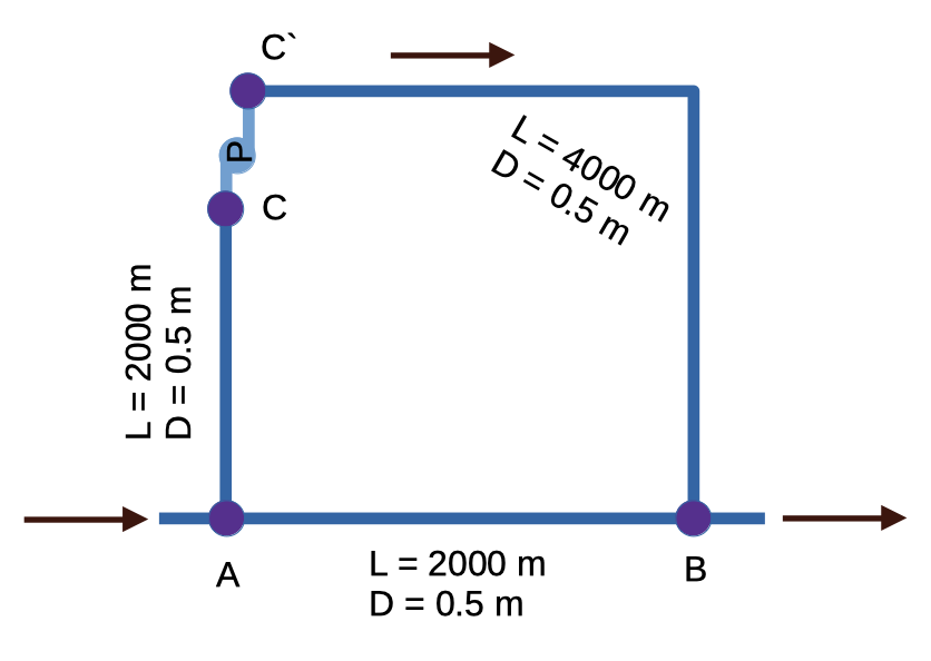
The figure below is a schematic of a parallel pipe system. Flow occurs from A to B as shown. To augment the flow a pump is located between C and C'. The network is on a plane (flat) surface; all the junction elevations are the same. The pipes are commercial steel.

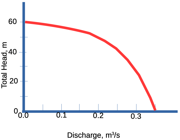
The pump characteristic curve is shown below:

Total discharge is 0.60 $\frac{m^3}{sec}$
Determine:
- The division of flow between pipes A-B and A-C-B
- The head loss in pipe A-B
- The head loss in pipe A-C
- The head loss in pipe C'-B
- The pump operating conditions.
sketch(s) here
list known quantities
list unknown quantities
governing principles
solution (step-by-step)
# script (code) here
discussion